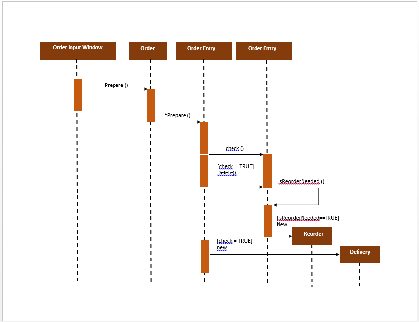

Lifelines and messages form the core of a sequence diagram. The messages appear in a sequential order on the lifeline.

Messages – Communication between objects is depicted using messages.The following is an example of a sequence diagram: Figure – a sequence diagram Difference between a lifeline and an actor – A lifeline always portrays an object internal to the system whereas actors are used to depict objects external to the system. If we want to model an unnamed instance, we follow the same pattern except now the portion of lifeline’s name is left blank. The head is located on top of a vertical dashed line (referred to as the stem) as shown above.

The standard in UML for naming a lifeline follows the following format – Instance Name : Class Name Figure – lifelineWe display a lifeline in a rectangle called head with its name and type. Lifeline elements are located at the top in a sequence diagram. So basically each instance in a sequence diagram is represented by a lifeline. Lifelines – A lifeline is a named element which depicts an individual participant in a sequence diagram.Figure – an actor interacting with a seat reservation system For example – Here the user in seat reservation system is shown as an actor where it exists outside the system and is not a part of the system. We can have multiple actors in a sequence diagram. We represent an actor in a UML diagram using a stick person notation. Figure – notation symbol for actorWe use actors to depict various roles including human users and other external subjects. It is important to note here that an actor is always outside the scope of the system we aim to model using the UML diagram. Actors – An actor in a UML diagram represents a type of role where it interacts with the system and its objects.
UML SEQUENCE DIAGRAM EXAMPLE SOFTWARE
These diagrams are widely used by businessmen and software developers to document and understand requirements for new and existing systems. Sequence diagrams describe how and in what order the objects in a system function. We can also use the terms event diagrams or event scenarios to refer to a sequence diagram. the order in which these interactions take place. Sequence Diagrams – A sequence diagram simply depicts interaction between objects in a sequential order i.e. Since visualizing the interactions in a system can be a cumbersome task, we use different types of interaction diagrams to capture various features and aspects of interaction in a system. Interaction diagram – An interaction diagram is used to show the interactive behavior of a system. A sequence diagram is the most commonly used interaction diagram. UML guides the creation of multiple types of diagrams such as interaction, structure and behaviour diagrams. Unified Modelling Language (UML) is a modeling language in the field of software engineering which aims to set standard ways to visualize the design of a system. In this post we discuss Sequence Diagrams. Design Patterns | Set 2 (Factory Method).Singleton Design Pattern | Implementation.SDE SHEET - A Complete Guide for SDE Preparation.Difference between Inverted Index and Forward Index.Introduction of Relational Model and Codd Rules in DBMS.Generalization, Specialization and Aggregation in ER Model.Conceptual Model of the Unified Modeling Language (UML).Unified Modeling Language (UML) | An Introduction.Unified Modeling Language (UML) | Object Diagrams.Unified Modeling Language (UML) | Activity Diagrams.Unified Modeling Language (UML) | State Diagrams.Unified Modeling Language (UML) | Sequence Diagrams.Unified Modeling Language (UML) | Class Diagrams.ISRO CS Syllabus for Scientist/Engineer Exam.ISRO CS Original Papers and Official Keys.GATE CS Original Papers and Official Keys.Like synchronous messages, they are drawn with an arrow connecting two lifelines however, the arrowhead is usually open. Reply (return) message is drawn with a dotted line and an open arrowhead pointing back to the original lifeline.Ĥ) Asynchronous messages don't need a reply for interaction to continue. It's usually drawn using a line with a solid arrowhead pointing from one object to another.Ī synchronous message we have in the steps # 1, 2, 4, 5, 7. They demonstrate how an object will behave in the context of the system.Ģ) A synchronous message requires a response before the interaction can continue.

You can see the steps 1 to 8.Įmployee, Bank IT System, Identity Management System are Objects. In this UML Diagram you can see how a BankĬustomer wants to transfer money abroad.


 0 kommentar(er)
